The goal
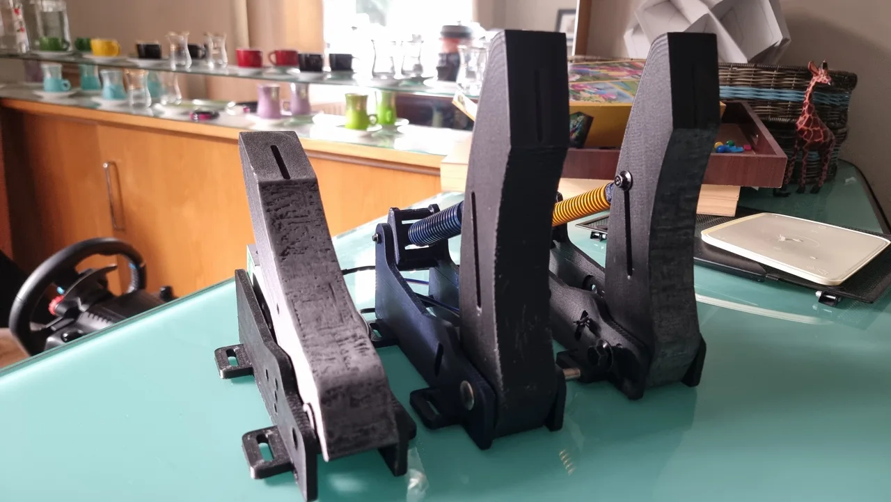
Build a three-pedal sim racing set with a force-sensitive brake and scope to adjust the geometry and spring arrangement. I used an open-source pedal guide as the structural starting point, then worked on the sensing and tried a copper finish on the printed pedal faces.
Sensing and assembly
| Pedal | Sensor | Design choice |
|---|---|---|
| Brake | Load cell | Measures applied force for the braking input |
| Throttle | Potentiometer | Measures pedal position |
| Clutch | Potentiometer | Measures pedal position |
The parts were printed in PETG-CF on my modified Ender 3 V3 SE and assembled with off-the-shelf fasteners and return springs. The brake used a heavier spring than the throttle and clutch.
The load-cell amplifier provides the brake signal. Further filtering and calibration would help characterise its behaviour at low forces; I have not presented a measured accuracy or durability result for the pedal set.
Copper electroplating experiment
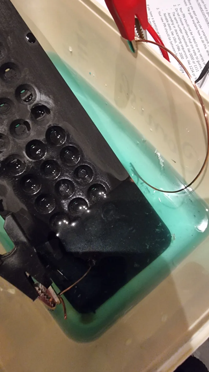
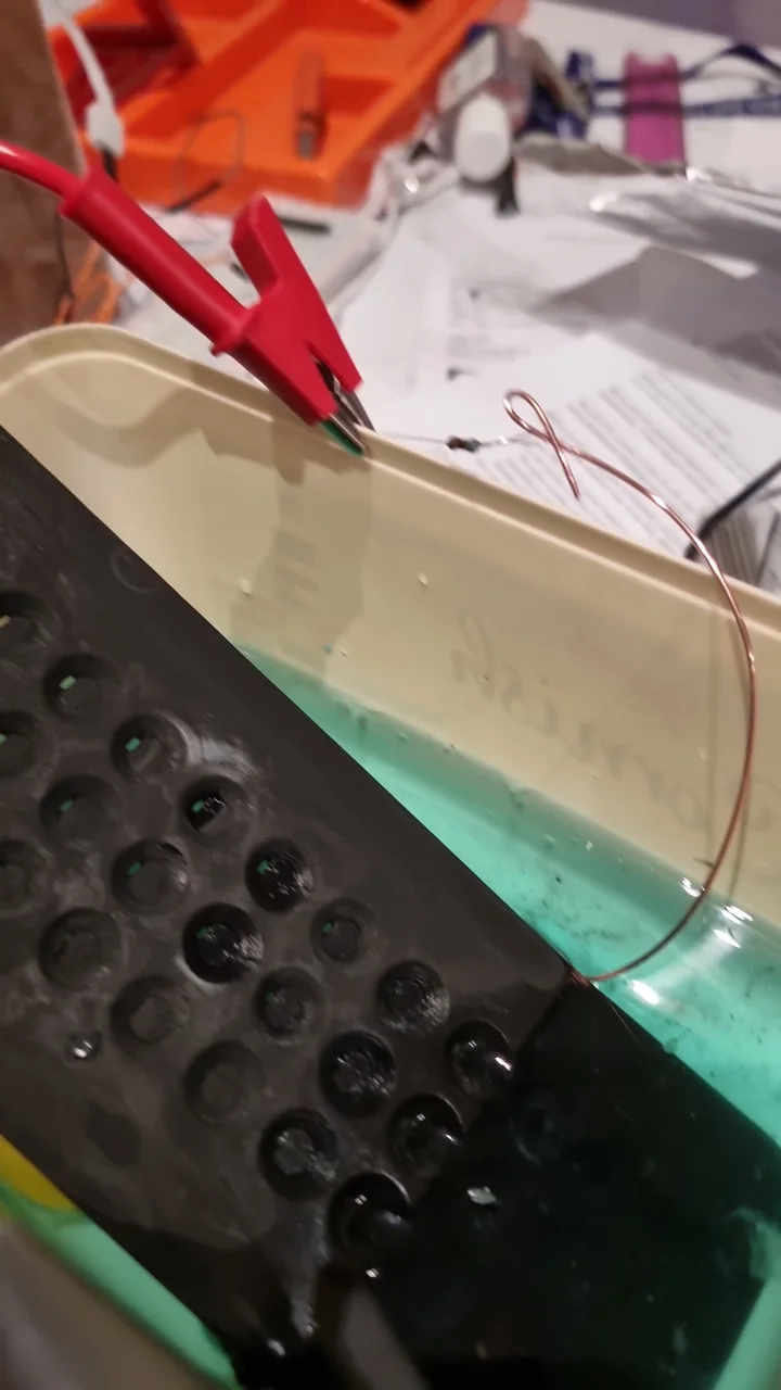
I coated a printed pedal face with conductive paint and tried copper deposition using a copper sulphate electrolyte and a copper anode. The aim was to explore whether a metal coating could improve the contact surface.
The result was partial coverage. Copper deposited in places, but the finish was uneven. Inconsistent conductivity in the painted layer appeared to be one contributor. A more uniform conductive coating is the next change I would test.
What I would improve
- Replace the throttle and clutch potentiometers with Hall-effect sensing.
- Compare coating methods before repeating the electroplating experiment.
- Refine load-cell calibration and filtering.
- Add a shared mounting plate with adjustable pedal spacing.
This build gave me a useful combination of mechanical assembly, sensor integration and an experimental manufacturing process whose first result still needed work.